I2C Pressure Sensor

Description

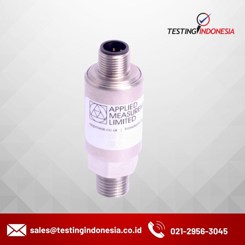
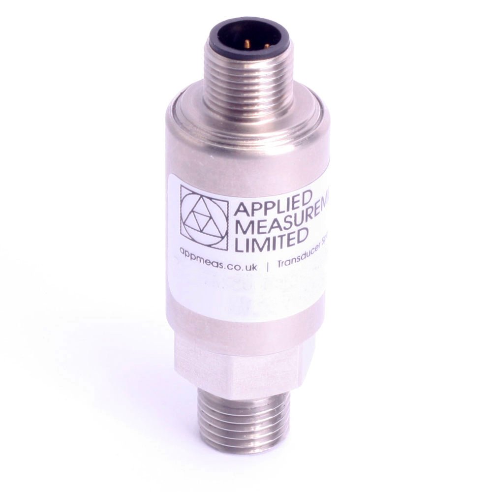
Applied Measurements I2C pressure sensor Pa6DC uses an I2C (Inter-Integrated Circuit) protocol to communicate with the Master Controller.  The I2C output is ideal for OEM, machine feedback systems, control systems and automation applications.

The benefit of using a pressure sensor with an I2C interface is that can be supported along with many I2C devices on the same circuit. I2C protocol allows an unlimited number of master devices to communicate with a maximum of 1008 slave devices on the bus. For example one Master with one Slave, multiple Masters with a single Slave, a single Master with multiple Slaves, or a Multi-Master with multiple Slaves. The I2C gas pressure sensor is designed to work as a Slave on an I2C protocol bus.

Product Dimensions

I2C Pressure Sensor Pa6DC M12 Outline

I2C Pressure Sensor Pa6DC M12 Outline

I2C Pressure Sensor Pa6DC Gland Outline

I2C industrial pressure sensor gland outline drawing

WIRING DETAILS

Electrical Connection Type +ve Supply -ve Supply SDA SCL
M12x1 Connector Pin 1 Pin 2 Pin 3 Pin 4
Cable Gland Red Blue Green Yellow

Features

  • Ranges: 0-500mbar up to 0-700bar
  • Output: I2C
  • Environmental Protection: IP65 (IP67 optional)
  • Accuracy: <±0.25%/FS (<±0.1% optional)
  • Stainless Steel Construction
  • UK-Made

Spesification

Nominal Pressure Range Bar (gauge, absolute or sealed gauge) 0-0.5 0-1 0-2 0-5 0-10 0-20 0-50 0-100 0-250 0-400 0-600 0-700
Compound Ranges Bar - -1…0 * -1…+2 * -1…+5 -1…+9 -1...+19 -1...+29 - - - - -
Permissible Overpressure Bar 1 2 4 10 20 40 100 200 400 575 800 800
Burst Pressure Bar 2 4 5 12 25 50 120 250 500 650 950 950
*<±0.1% / FS (BFSL) accuracy not possible in these ranges
Output Signal & Supply Voltage Wiring System Output Supply Voltage Input Current
Pa6DC 4-wire I2C 2.7-5.5Vdc <3mA
Performance
Accuracy (non-linearity, hysteresis, repeatability) % Full Scale Output <±0.25 (BFSL) <±0.1 (BFSL) optional
Zero Balance ±% of Rated Output <1.0
Setting Errors (offsets) Zero & Full Scale, <±0.5% / FS
Influence Effects Supply Effects <0.005 % FS / 1V
Response Time (10% - 90%) ms ≤10
Warm-Up Time ms 500 typ.
Permissible Temperatures & Thermal Effects
Media Temperature (Note: subject to 'O' ring seal, see below) ˚C -40 to +135
Ambient Temperature ˚C -20 to +85
Storage Temperature ˚C -20 to +85
Compensated Temperature Range ˚C +20 to +80
Thermal Zero Shift (TZS) % / FS / ˚C <±0.04 (standard) <±0.02 (option) <±0.01 (option)
Thermal Span Shift (TSS) % output / ˚C <-0.015
Electrical Protection
Reverse Polarity Protection No damage but also no function
Electromagnetic Compatibility CE Compliant
Insulation Resistance Megohms Ω at 50V dc >500
Mechanical Stability
Shock 100 g / 11 ms
Vibration 10 g RMS (20 ... 2000 Hz)
Materials
Housing & Process Connection 303 Stainless Steel 316L Stainless Steel (optional)
‘O’ Ring Seals (inc. Temperature Range) Viton (-20ºC to +135ºC) NBR/Nitrile (-40ºC to +100ºC) (optional) EPDM (-40ºC to +130ºC) (optional) Chemraz (-10ºC to +135ºC) (optional)
Diaphragm Ceramic Al2O3 96 %
Media Wetted Parts Housing and process connection, ‘O’ ring seal, diaphragm
Misc
Weight grams 100 nominal
Installation Position Any
Operational Life pressure cycles > 100 x 106
Environmental Protection Cable Gland M12 x 1 Connector M12 x 1 Connector IP65 Gauge Reference ≤ 50bar : IP65 / Absolute, Sealed Gauge or >50bar Range : IP67