
Description
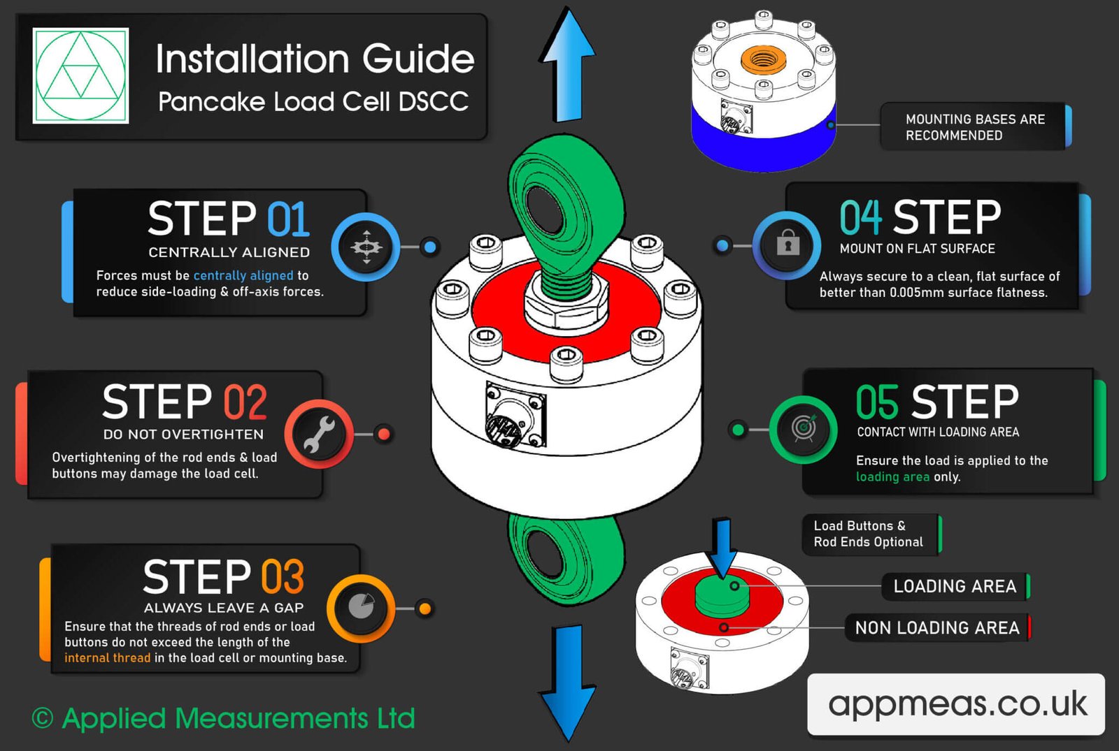
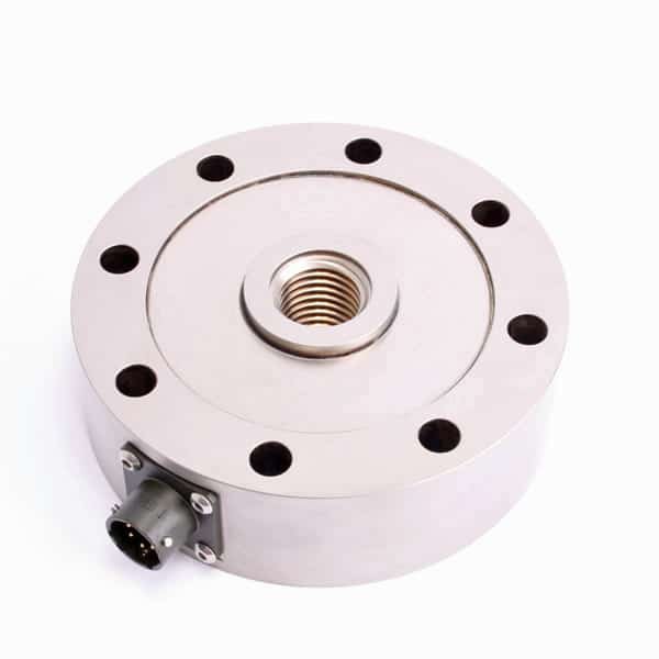
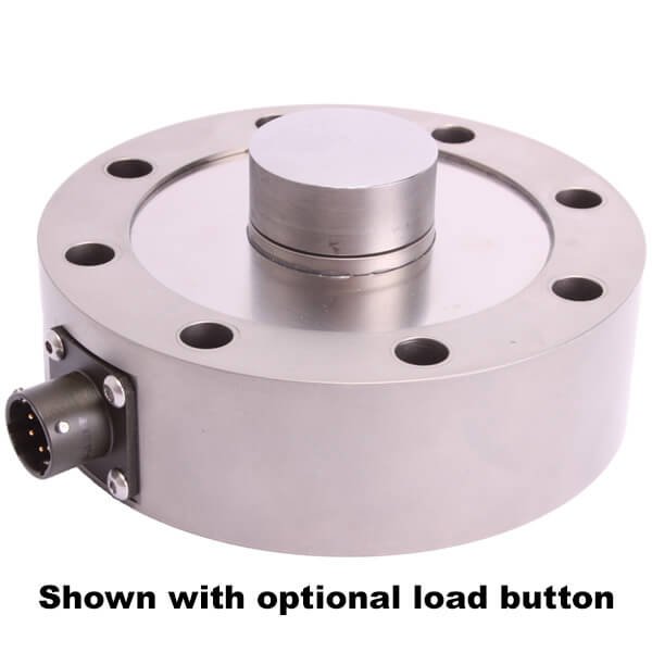
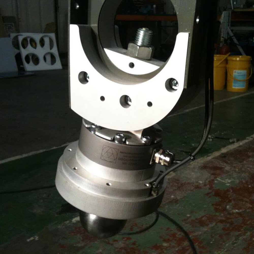
The DSCC pancake load cell / low profile load cell by Applied Measurements is manufactured in stainless steel and is suitable for use in weighing and force measurement applications. Our pancake load cells are available to buy online with capacities 0-200kN in stock.
The DSCC can operate in both tension and compression and are commonly used in materials testing and component fatigue testing applications for axial force measurements where a high accuracy, low-profile device is required.
The high-frequency response of the DSCC pancake load cells also makes them ideal for dynamic force and load measurement applications such as crash test walls. The high-speed analogue SGA amplifier is an ideal complement to the DSCC pancake load cell, offering a conditioned signal output of 4-20mA, ±5Vdc or ±10Vdc with a bandwidth of up to 6kHz.
Thanks to the pancake load cell’s dual-diaphragm design and central threaded through-hole, it is largely insensitive to bending, off-axis, bending, side-load/shear loads and torsion.
As with all Applied Measurements pancake load cell designs, the DSCC low profile load cell can be modified to suit your specific requirements, with alternative threads, custom dimensions, counter-bored mounting holes and higher capacities in excess of 3000kN possible.
Plus, for harsh, wet or humid environments we can make gel-filled pancake load cells rated to IP67. IP68 immersion versions are suitable for complete submersion and can also be offered on request.
Our DSCC pancake load cell can be supplied with a BS EN ISO 376 calibration certificate for use as a reference standard.
Product Dimensions
| Core Product Ref | CAPACITY (kN) | ØA (Size) | B | C | ØD | ØE | Thread F | ØG | N holes | H | J |
|---|---|---|---|---|---|---|---|---|---|---|---|
| DSCC | 0-5, 0-10, 0-25, 0-50 | 107 | 2 | 33 | 8.5 | 33 | M20 x 2.5 | 90 | 8 | 35 | 2 |
| DSCC | 0-100, 0-200, 0-250 | 155 | 3 | 45 | 11 | 60 | M36 x 2 | 130 | 12 | 45 | 2 |
| DSCC8 | 0-250, 0-300, 0-500 | 202 | 2 | 52 | 12.2 | 95.5 | M56x4 | 165 | 16 | 50 | 2 |
| DSCC | 0-300, 0-500, 0-750, 0-1000 | 278 | 6 | 78 | 17 | 118 | M64 x 6* | 230 | 16 | 84 | 4 |
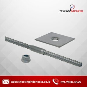
| *If you require rod end bearings please request an M64 x 4 thread. Note that the maximum rated safe static load on this size rod end is 689kN. | |||||||||||
All dimensions are in mm
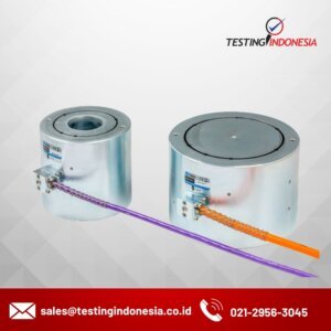
Wiring Details (Single Bridge Version)
| Wire | Connector Pin | Designation |
|---|---|---|
| Red | Pin A | +ve excitation |
| Blue | Pin B | -ve excitation |
| Green | Pin C | +ve signal (compression) |
| Yellow | Pin D | -ve signal |
| Screen | N/C | To ground – not connected to load cell body |
Wiring Details (Dual Bridge Version)
| Wire | Connector Pin | Designation |
|---|---|---|
| Red | Pin 8 | +ve excitation (bridge A) |
| Blue | Pin 7 | -ve excitation (bridge A) |
| Green | Pin 3 | +ve signal (compression) (bridge A) |
| Yellow | Pin 4 | -ve signal (bridge A) |
| Brown | Pin 2 | +ve excitation (bridge B) |
| White | Pin 1 | -ve excitation (bridge B) |
| Pink | Pin 6 | +ve signal (compression) (bridge B) |
| Grey | Pin 5 | -ve signal (compression) |
| Screen | N/C | To ground – not connected to load cell body |